

Mechanical mechanisms are assemblies of parts — such as screws, belts, gears, cams, linkages, pulleys and flywheels — that convert one type of motion into another or transmit and amplify force in a controlled, repeatable way. They are the building blocks of every machine, from pick-and-place units and indexing tables to presses, conveyors and engines.
This guide explains the main types of mechanical mechanisms, how they work, where they are used and how to choose the right one for your machine design.
What are mechanical mechanisms?
A mechanical mechanism converts the motion of a drive — usually the rotation of a motor or the stroke of a cylinder — into the motion a machine needs: linear, intermittent, reciprocating, synchronised or amplified. Typical components are ball screws, timing belts, racks and pinions, cams, Geneva drives, linkages, pulleys and flywheels.
Choosing the right mechanism determines the accuracy, speed, cost and service life of a machine. Understanding how each mechanism behaves helps engineers create clear technical drawings and machines that are precise, efficient and easy to maintain.
Types of mechanical mechanisms
Mechanisms can be grouped by their drive source — rotary or linear — and by the motion they produce:
| Drive | Output motion | Mechanisms | Typical examples |
|---|---|---|---|
| Rotary | Linear | Ball screw, timing belt, rack and pinion | Linear actuators, gantries, positioning tables |
| Rotary | Intermittent | Cam indexer, Geneva drive | Rotary indexing tables, assembly machines |
| Rotary | Reciprocating or oscillating | Cam, electronic cam, linkage, lead or ball screw | Windscreen wipers, table lifters, scissor jacks, gear shifters |
| Rotary | Synchronised | Line shaft | Conveyors, packaging machines |
| Rotary | Amplified force | Pulleys and block and tackle | Cranes, hoists |
| Rotary | Stabilised rotation | Flywheel | Engines, presses, sewing machines |
| Linear | Rotary | Slider-crank, rack and pinion | Combustion engines, pneumatic rotary actuators |
Converting rotary motion to linear motion
Converting the rotation of a servo or stepper motor into linear motion is one of the most common tasks in automation. Three mechanisms dominate:
| Mechanism | Positioning accuracy | Stroke | Advantages | Disadvantages |
|---|---|---|---|---|
| Ball screw | Very high | Short to medium | High accuracy and rigidity, high thrust, high acceleration | Long screws whip at high speed, rolling noise, higher cost |
| Timing belt | Medium | Long | High speed, long strokes, quiet, low cost, no lubrication | Belt elasticity reduces accuracy and stiffness at high acceleration |
| Rack and pinion | Medium | Very long (modular) | High speed and force, practically unlimited stroke, high acceleration | Needs lubrication, backlash, noise and wear particles |
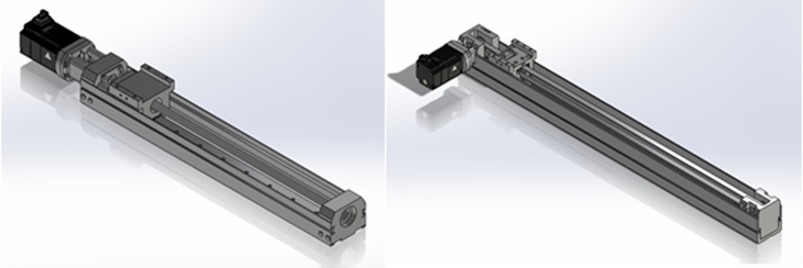
Note that the motor is mounted differently: on ball screw actuators it usually sits in line with the screw, while on belt-driven actuators it is often mounted at the side or folded back. Plan the installation space accordingly.
Linear motors are a growing alternative. They drive the carriage directly without mechanical transmission, offering very high accuracy, speed and quiet operation — at a higher cost and with permanent magnets made from rare-earth materials.
How to choose:
- Ball screw for high accuracy and high thrust.
- Timing belt for low cost, high speed and long strokes.
- Rack and pinion for very long strokes and high forces, e.g. in gantries.
Converting rotary motion to intermittent motion
Intermittent motion — move, stop, move — is the basis of indexing tables and assembly machines. Cam indexers and Geneva drives convert the continuous rotation of a motor into precise steps with defined dwell times.
| Mechanism | Advantages | Disadvantages |
|---|---|---|
| Cam indexer | Smooth, jerk-free motion; index angle, dwell time and motion profile freely defined by the cam | Complex cam shape increases machining cost; difficult to modify later |
| Geneva drive | Simple design, low cost | Abrupt acceleration at the start and end of each step; fixed number of stations |
Define the requirements of an indexer — number of stations, index time, acceleration profile and load — early in the design, because changes later are difficult. Zero-backlash versions are available for servo-driven systems.
Linkages: changing direction and range of motion
Linkages connect rigid links with joints to change the direction, range and force of a motion. They convert rotation into reciprocating motion, guide parts along defined paths or multiply force. In practical design, two aspects matter most: how the output moves, and the mechanical advantage (lever ratio).
- Windscreen wiper: the motor drives a short crank, which moves a longer rocker back and forth. Because the crank is shorter than the rocker, the continuous rotation becomes an oscillating sweep.
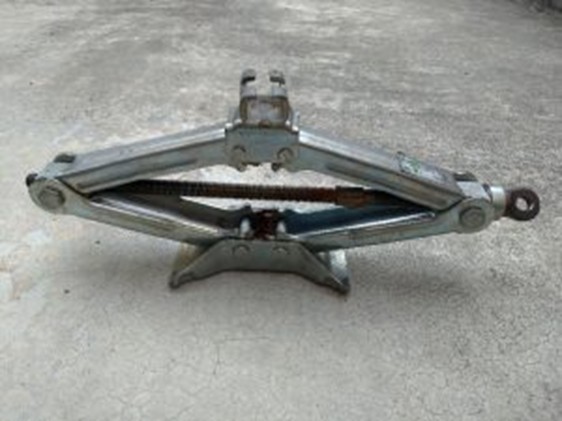
- Scissor jack: turning the screw pulls the joints of the scissor structure together and lifts the load. The lifting force is F = T × tan θ, where T is the axial force in the screw and θ is the angle of the arms to the horizontal — the jack is easiest to operate when it is extended.
- Motorcycle gear shifter: pressing the L-shaped pedal moves a connecting rod, which swings a lever on the gearbox shaft and changes the gear.
Linkages are easy to test with cardboard models or 3D CAD motion studies, which also allow stress analysis of each link under load.
Cam mechanisms
A cam converts rotation into a precisely defined reciprocating or oscillating motion of a follower. The cam profile determines the path, speed and dwell of the follower. The most common types are:
- Plate (disc) cams: e.g. for valve actuation in combustion engines.
- Groove cams and barrel cams: the follower runs in a groove, e.g. in indexing mechanisms.
The follower is usually kept in contact with a plate cam by a spring. At high speeds, the spring force may no longer be enough, and the follower lifts off the cam — known as follower jump or, in engines, valve float. Groove cams avoid this because they guide the follower positively in both directions.
Mechanical cams are ideal for fixed, repeating motion sequences. With today's high-mix, low-volume production, they are increasingly replaced by servo motors with electronic cam (e-cam) functions: the controller follows a virtual cam profile that can be changed in software within minutes — more flexible, but more expensive.
Synchronising rotary motion: line shafts
A line shaft drives several stations of a machine or conveyor from a single motor. The motor turns a long shaft, which passes motion on via round belts on small conveyors or bevel gearboxes on larger ones. Couplings connect shaft sections for long systems.
- All stations run in perfect synchronisation.
- Simple control and fewer electrical components.
The drawback is low flexibility: changing the layout later is difficult. With affordable motors and drives, line shafts are less common today, but they are still used in conveyors. Classic packaging machines, such as bottle case packers, combined line shafts and cams to align, handle, pack and discharge products.
Multiplying force: pulleys
Pulleys change the direction and magnitude of a force. A fixed pulley only changes the direction: lifting a 10 kg load (98 N) still requires 98 N. A movable pulley hangs on two rope sections, so each carries half the load — the required force is only 49 N, but the rope must be pulled twice as far. Cranes and hoists combine several pulleys in a block and tackle to multiply the force further.
| Mechanism | Advantages | Disadvantages |
|---|---|---|
| Pulley and block and tackle | Changes the direction of force and multiplies it | Longer rope travel; the rope must stay under tension or it can jump off the pulley |
Stabilising rotary motion: flywheels
A flywheel stores rotational energy and smooths out speed fluctuations. In a four-stroke engine, only one of four strokes delivers power — the crankshaft turns twice per power stroke — so the flywheel carries the engine through the other strokes. Presses use flywheels to deliver short, high-energy strokes from a relatively small motor.
The inertia must be chosen carefully:
- Too much inertia: slow acceleration and sluggish response.
- Too little inertia: the speed falls under load and the motion becomes uneven.
The same applies to servo drives: pulleys, gears and other rotating parts add inertia, so the ratio of load inertia to motor inertia must be kept within the motor manufacturer's recommendations.
Converting linear motion to rotary motion
The slider-crank converts linear motion into rotation, and vice versa. In an engine, the piston is pushed down by combustion, and the connecting rod turns the crankshaft. In a crank press, the process is reversed: the rotating crank drives the ram up and down.
Rack and pinion systems also work in both directions, for example in pneumatic rotary actuators or rotating stages. They generate high torque, and a design with two racks and one pinion balances the forces and relieves the shaft of bending loads.
| Mechanism | Advantages | Disadvantages |
|---|---|---|
| Slider-crank | Simple, robust, works in both directions | Output speed is not uniform even at constant input speed |
| Rack and pinion | High torque, readily available components | Stroke or rotation angle is fixed by the rack length |
Custom parts for mechanical mechanisms with meviy
Every mechanism combines standard components — ball screws, belts, bearings, gears — with parts designed for the specific machine. meviy, the on-demand manufacturing platform by MISUMI, produces these individually designed parts directly from your 3D CAD data — not catalogue or standard parts:
- CNC milling: cam plates, links and levers, motor brackets, base plates and mounting blocks.
- CNC turning: shafts, hubs, spacers, rollers and flywheels.
- Sheet metal fabrication: brackets, covers, guards and frames.
Upload your model and get the price and lead time instantly — ideal for prototypes and machine builds where every part is different. Learn more about CNC machining with meviy.
Frequently asked questions about mechanical mechanisms
What are mechanical mechanisms?
Mechanical mechanisms are assemblies of parts that convert one type of motion into another or transmit and amplify force. Examples include ball screws, timing belts, rack and pinion drives, cams, Geneva drives, linkages, pulleys and flywheels.
How do you convert rotary motion to linear motion?
The most common mechanisms are ball screws, timing belts and rack and pinion drives. Ball screws offer the highest accuracy, timing belts are fast and low-cost for long strokes, and rack and pinion drives suit very long strokes and high forces.
What is the difference between a cam indexer and a Geneva drive?
Both convert continuous rotation into intermittent steps. A cam indexer produces smooth, freely definable motion but costs more. A Geneva drive is simpler and cheaper but accelerates abruptly at the start and end of each step.
What is an electronic cam?
An electronic cam (e-cam) replaces a mechanical cam with a servo motor that follows a cam profile stored in the controller. The motion can be changed in software, which makes it ideal for frequent product changes.
What does a flywheel do?
A flywheel stores rotational energy and keeps the speed of a machine steady. It carries engines through the strokes without combustion and supplies short bursts of energy in presses.
Conclusion
Mechanical mechanisms convert and transmit motion and force in every machine. Ball screws, belts and racks create linear motion; cams and Geneva drives create intermittent steps; linkages change direction and force; line shafts synchronise; pulleys multiply force; flywheels stabilise rotation; and slider-cranks turn linear motion into rotation. Knowing their strengths and weaknesses makes it easier to design machines that are precise, robust and cost-effective.