Projects don't take holidays – save EUR 200

Suppliers close in August. meviy doesn’t. Upload CAD, get EUR 200 off orders above EUR 200. 15 Jul–31 Aug. T&Cs apply.

×

Manufacturing innovation, built into your price

Milling Parts Standard shipping now runs more competitively on orders with larger quantities, powered by smarter automation.

×

Design Tips

Instant Quotation for your Milled Parts

With meviy, you can order your custom cnc milled parts quickly and easily online by uploading your 3D CAD file. Below you will find general tips on the design of your cnc milled parts and how you can design them more efficiently and cost-effectively.

Typical Errors when creating a Quote with meviy

The uploaded 3D-CAD file could not be read by meviy

If you encounter following error codes

1. the file format could not be read
2. PMI could not be calculated

this means that you are using 3D CAD formats and extensions that are not supported by meviy. To solve this problem, we recommend that you check and adjust the list of formats supported by meviy.

These formats are supported by meviy:

  • Autodesk Inventor 2023 and previous versions (.ipt)
  • CATIA V5-6R2022 and previous versions (.CATpart)
  • Creo – Pro/E 19.0 to Creo 9.0 (.prt/.neu/.xpr)
  • NX – Unigraphics (.prt)
  • SolidEdge V19-20 / ST10 and previous versions (.par/.pwd)
  • SOLIDWORKS 2023 and previous versions (.sldprt)
  • I-deas (.arc/.unv)
  • iCAD SX V8L3 and previous versions (.icd)
  • STEP AP203, AP214 (.step/.stp)
  • Parasolid (.x_t/.x_b/.xmt/.xmt_txt)
  • ACIS (.sat/.sab)
  • JT (.jt)
  • PRC (.prc)

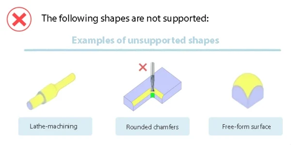
This error is caused by uploading a form that is not available for an instant quote with meviy. To solve this problem, please check the available forms that we can offer with meviy.

Unsupported shapes in CNC manufacturing shown with warning icon, including lathe-machined parts, rounded internal chamfers, and free-form curved surfaces that are not supported by the platform.

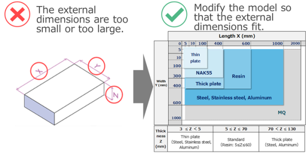
This error is caused by the size of the uploaded part. If the uploaded part is outside the size for the instant quote area, no quote can be created. In this case, the dimensions of the part must be adjusted. Please check our available sizes.

Illustration showing unsupported external dimensions in CNC manufacturing, with a warning that part size is too small or too large, and a reference chart displaying maximum and minimum length, width, and thickness limits for materials such as steel, stainless steel, aluminum, and resin.

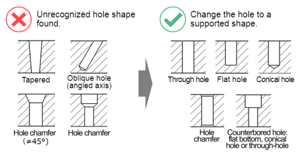
This error occurs when a part is uploaded whose hole types cannot be recognized by our meviy system. In this case, the hole is not supported and must be changed to one of the supported hole types. Please check our available hole types.

Diagram showing unsupported and supported hole geometries in CNC machining. Unsupported hole shapes include tapered holes, oblique angled holes, and incorrect hole chamfers. Supported hole types include standard through holes, flat-bottom holes, conical holes, and counterbored holes with flat or conical bottoms.

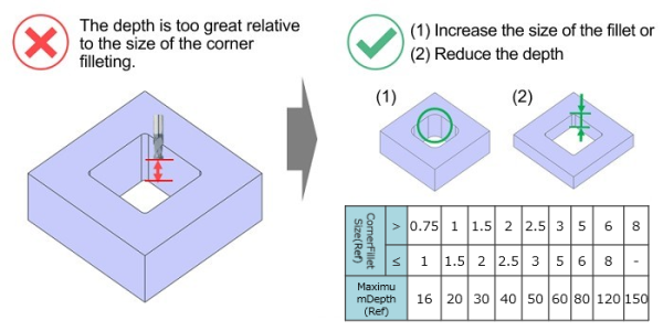
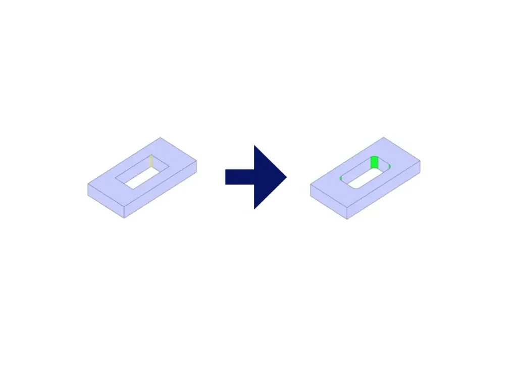
Such an error occurs when the corner radius within the so-called pocket cannot be manufactured with the given tools. To solve this problem, it is advisable to adjust the corner radius accordingly. One way of doing this would be to increase the corner radius so that the milling cutter can manufacture the corner radius.

CNC milling design guideline diagram showing pocket depth too great relative to corner fillet radius, end mill limitation in deep internal corners, and recommended solutions to increase fillet size or reduce pocket depth with reference table for maximum depth by fillet radius.

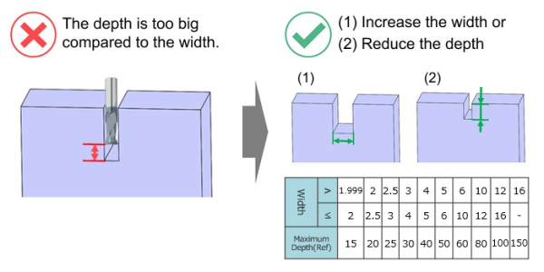
This error occurs if the specified machining depth is deeper than the width of the pocket allows. The tool diameter is determined by the minimum pocket width. A smaller pocket width means that a narrower end mill must be selected, preventing deeper machining. To solve this problem, it is advisable to increase the pocket width or reduce the pocket depth. By increasing the pocket width or reducing the pocket depth, you can ensure that machining can be carried out properly.

Illustration showing a CNC milling slot where the pocket depth is too large compared to its width. The diagram highlights an excessive depth-to-width ratio and recommends increasing the slot width or reducing the machining depth to meet CNC design and manufacturability guidelines.

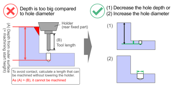
This error occurs when the hole is deeper than intended, which can lead to a collision between the spindle and the workpiece. To eliminate this problem, it is advisable to adjust the depth, diameter or position of the hole to avoid a collision and ensure a smooth machining process.

CNC machining diagram showing hole depth too large compared to hole diameter, tool holder collision risk, tool length versus machining start height, and design solutions to decrease hole depth or increase hole diameter to avoid interference.

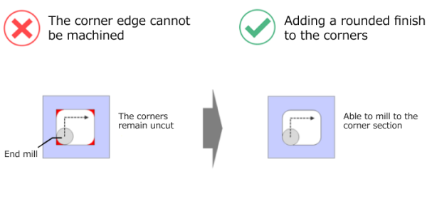
This error occurs if an inner corner angle does not have a radius and therefore a radius remains in the corners. To correct this problem, the suggested radius can be used to round the corner. Alternatively, it may be necessary to adapt the design in order to shape the corner so that it meets the requirements and does not have any unwanted radii.

Diagram illustrating a CNC machining limitation where sharp internal corner edges cannot be fully milled with an end mill. The graphic shows that square internal corners remain uncut and recommends adding a rounded corner radius to enable proper CNC milling of the corner section.

Design Tips for CNC-Milling Parts: Pockets and Radii

The design of the pockets and the corresponding corner radii is of paramount importance. These aspects not only contribute to the overall aesthetic effect, but also play a crucial role in ensuring optimal functionality and manufacturability of individual milled parts. In this section, we will look at basic design knowledge and guide you through the art of creating pockets in milled parts that seamlessly combine form and function while taking into account the intricacies of corner radii. To help you create an instant quote for your specific milled part, we’ll explore three different types of pockets: closed pockets, open pockets and stepped pockets.

closed-pocket

Closed pockets

In a closed pocket, where all four sides are closed, the movement of the end mill follows a pattern as shown in the illustration. This type of movement means that angles smaller than the end mill diameter cannot be machined. For this reason, it is essential to provide an inside radius at all four corners.

open-pocket

Open pockets

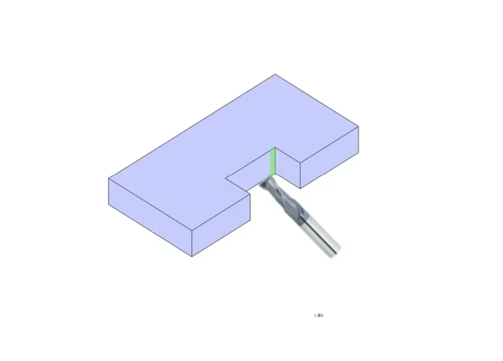
In an open pocket, where the four surrounding sides are not closed, it is possible to machine pocket shapes without an inner radius, as these can be machined horizontally. However, this requires careful planning of the entry direction of the cutting tool.

Stepped pocket

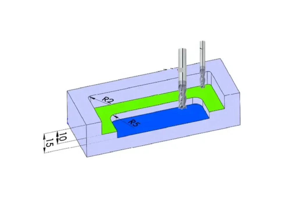
With a stepped pocket, as shown below, the flatter pocket is specified with a corner radius of R2. This enables machining with an end mill designed for a radius of R2. The deeper pocket, on the other hand, is specified with a corner radius of R5 and requires correspondingly adapted machining tools. As the depth increases, an end mill with a larger diameter is required, which ensures careful machining.

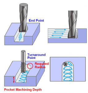
CNC milling pocket machining diagram showing end point, turnaround point, required radius and pocket machining depth

Radius at the turning point of the end mill

A radius corresponding to the end mill is always required at the end and turning points of the end mill. The following figure illustrates the behavior of the end mill at these points. The required radius value varies depending on the depth of the pocket in order to enable machining with the optimum diameter of the end mill.

Ready to order?