Projects don't take holidays – save EUR 200

Suppliers close in August. meviy doesn’t. Upload CAD, get EUR 200 off orders above EUR 200. 15 Jul–31 Aug. T&Cs apply.

×

Manufacturing innovation, built into your price

Milling Parts Standard shipping now runs more competitively on orders with larger quantities, powered by smarter automation.

×

DESIGN TIPS

Instant Quotation for your Sheet Metal Parts

With meviy, you can order your custom sheet metal parts quickly and easily online by uploading your 3D CAD file. Below you will find general tips on the design of your sheet metal parts and how you can design them more efficiently and cost-effectively.

If you still have questions about meviy, please contact our meviy support.

Typical Errors when creating a Quote with meviy

The uploaded 3D CAD file could not be read by meviy

The uploaded 3D-CAD file could not be read by meviy

If you encounter following error codes

1. the file format could not be read
2. PMI could not be calculated

this means that you are using 3D CAD formats and extensions that are not supported by meviy. To solve this problem, we recommend that you check and adjust the list of formats supported by meviy.

These formats are supported by meviy:

  • Autodesk Inventor 2023 and previous versions (.ipt)
  • CATIA V5-6R2022 and previous versions (.CATpart)
  • Creo – Pro/E 19.0 to Creo 9.0 (.prt/.neu/.xpr)
  • NX – Unigraphics (.prt)
  • SolidEdge V19-20 / ST10 and previous versions (.par/.pwd)
  • SOLIDWORKS 2023 and previous versions (.sldprt)
  • I-deas (.arc/.unv)
  • iCAD SX V8L3 and previous versions (.icd)
  • STEP AP203, AP214 (.step/.stp)
  • Parasolid (.x_t/.x_b/.xmt/.xmt_txt)
  • ACIS (.sat/.sab)
  • JT (.jt)
  • PRC (.prc)

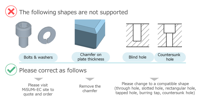
This error is caused by uploading a form that is not available for an automatic quote with meviy. To resolve this issue, please check the available shapes that we can offer with meviy.

Unsupported CNC design shapes including bolts, washers, chamfer on plate thickness, blind hole and countersunk hole with correction guidelines

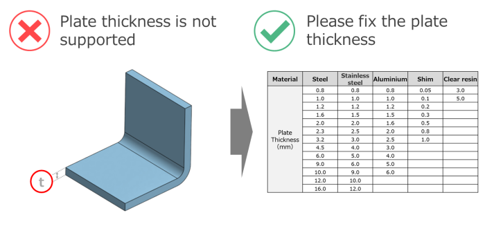
This error occurs if the desired sheet thickness is not supported. To solve this problem, please adjust the model so that it matches the available sheet thickness.

Unsupported sheet metal plate thickness example with correction table for compatible material thickness options

This error occurs if the sheet thickness is not constant during creation of the part or if the bending radius R is not within the possible range. To solve this problem, please adjust the model so that the sheet thickness is uniform.

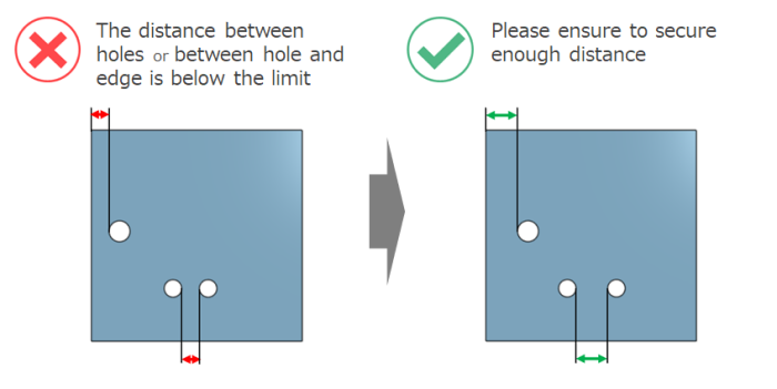
This error occurs if the distance between the holes and the edge, or between holes, is below the possible range. To solve this problem, please increase the distance between holes and the end faces or between the individual holes.

Sheet metal hole spacing below minimum edge distance with corrected example showing proper hole to edge and hole to hole spacing

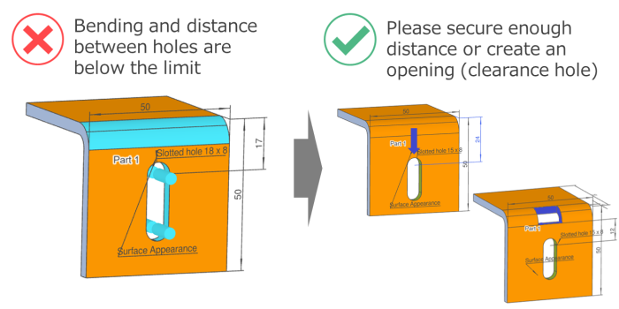
This error occurs if the distance between the bend and the hole is below the limit value. To rectify this problem, either increase the distance between the bend and the hole or create an opening at the bending edge (cut-out).

Sheet metal bend to hole distance below limit with corrected design using proper clearance and slot positioning

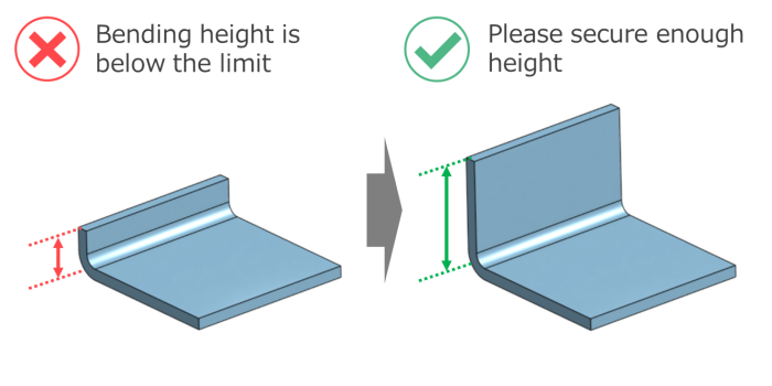
This error occurs if the bending height is below the limit value. To rectify this problem, increase the bending height to a suitable dimension. Detailed information can be found on our technical information page.

Sheet metal bending height below minimum limit with corrected design showing sufficient flange height
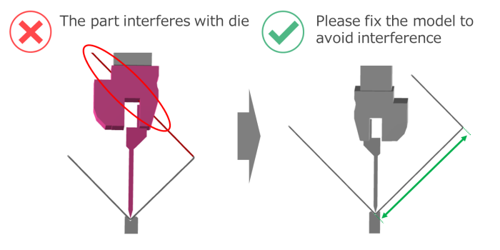
This error occurs when the component geometry causes interference during bending. To correct this problem, adjust the part in your 3D CAD file to avoid the interference. Detailed help is available on our technical information page.
Sheet metal part interfering with bending die showing model correction to prevent tooling collision

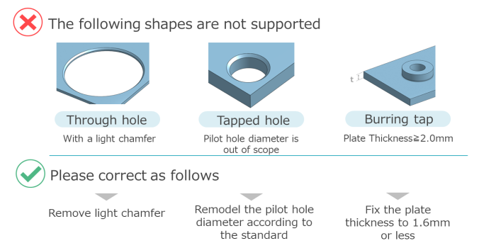
This error occurs if the shape of the hole is not recognised. To fix this, please change the hole to a supported shape and upload the file again.

Unsupported sheet metal hole types including chamfered through hole, tapped hole and burring tap with required design corrections

Rules for modelling when bending sheet metal

Bending

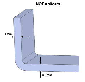
Non uniform sheet metal bend with inconsistent wall thickness dimensions 1mm and 0.8mm

The sheet thickness is not uniform

The sheet thickness must be the same on both sides. In the example on the left, the sheet metal part has a sheet thickness of 1 mm on one side and 0.8 mm on the other. To receive a quote for this sheet metal part and to enable manufacturing, both sides must have the same sheet thickness. For example, 0.8mm or 1mm on both sides. Please check your three-dimensional CAD file and upload the part to meviy again.

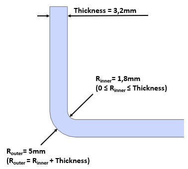
Sheet metal bend radius determination diagram showing thickness 3.2mm, inner radius 1.8mm and outer radius calculation

Determination of the radius

Always model the inside radius (R inner) of the bend as follows. The inner radius must be greater than or equal to the sheet thickness. The inner radius must also be smaller than the sheet thickness. Both values together should result in the outer radius (R outer).

R outer equals inside radius plus sheet thickness

Feed bending

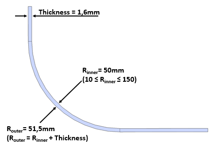
Sheet metal curved bending radius example with 1.6mm thickness, 50mm inner radius and outer radius calculation

Determination of the radius during feed bending

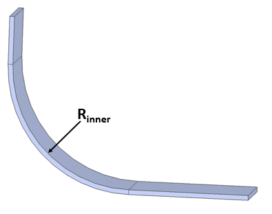
The inner bending radius should be at least ten, while the outer bending radius should correspond to the inner radius plus the sheet thickness. Please refer to the following section for the range of bending radii.

Sheet metal curved bend illustration highlighting inner bending radius R inner

The sheet thickness is not uniform

The sheet thickness must be the same on both sides. In the example on the left, you can see a bent sheet metal part with a sheet thickness of one millimetre on one side and nought-point-eight millimetres on the other. In order to receive a quote for this sheet metal part and to be able to manufacture it, both sides must have the same sheet thickness. For example, nought-point-eight millimetres or one millimetre on both sides. Please check your three-dimensional CAD file and upload the part to meviy again.

Ready to order?