


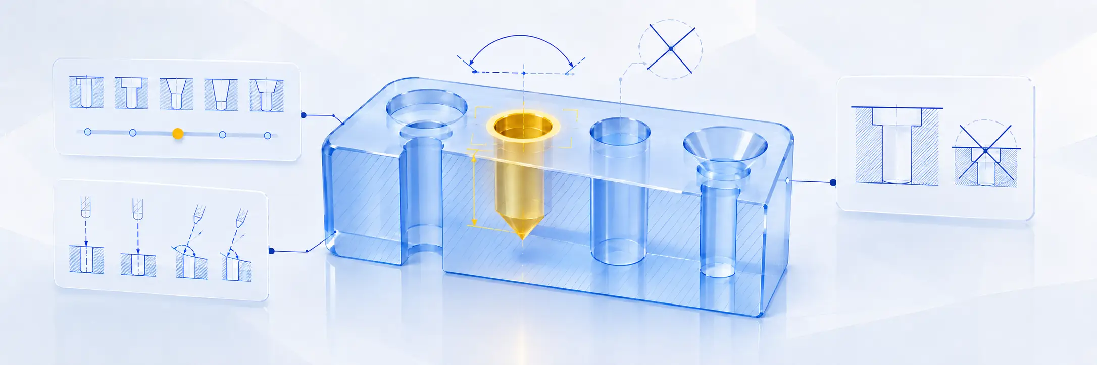
Designing holes for machined components seems straightforward — until a misplaced tolerance or an overlooked depth limit turns your part into scrap. Understanding how holes are actually manufactured helps you design parts that are easier, faster, and cheaper to produce.
In this guide, we cover the most common hole machining operations, explain what each one is used for, and highlight the design mistakes that cause the most problems on the shop floor. Whether you're specifying reamed bores, tapped threads, or simple through-holes, these principles will help you get it right the first time.
How holes are machined: the basic process
In CNC machining, creating a hole typically follows a sequence of operations rather than a single cut:
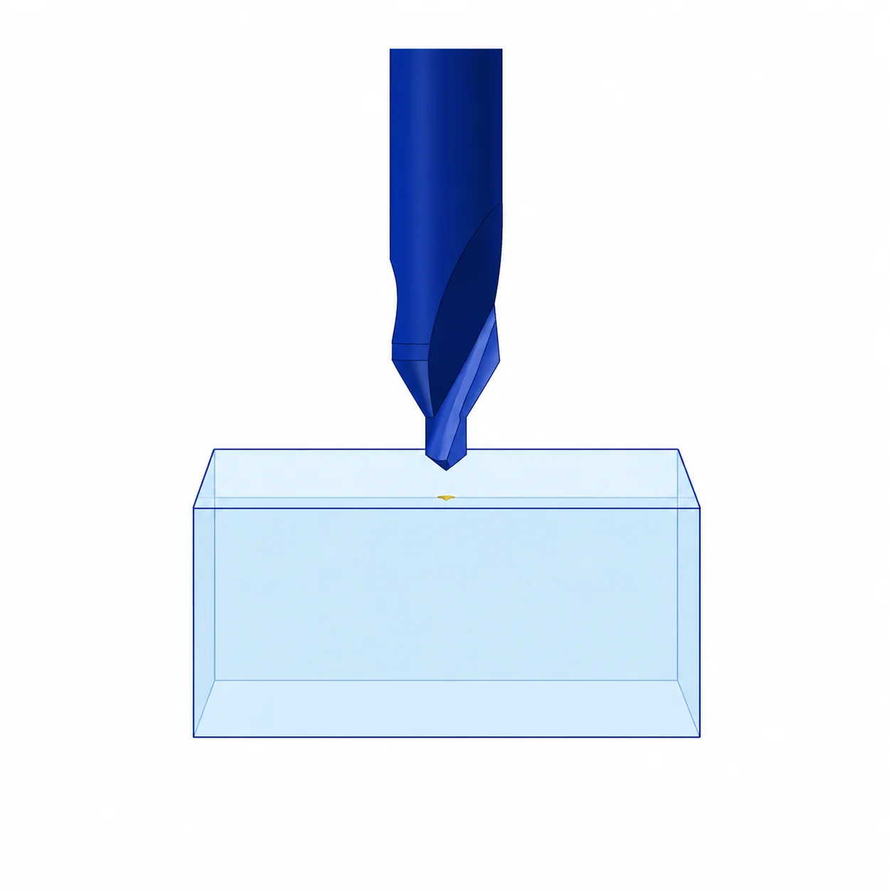
- A centre hole is drilled first. This small indentation guides the subsequent drill and prevents it from wandering across the surface.
- A pilot hole is drilled to the target diameter. At this stage the hole is functional but may have slight surface imperfections — this is often referred to as a "drilled hole" and is sufficient when tight tolerances are not required.
- A finishing operation is applied based on the hole's intended function. Depending on whether the hole needs to accept a pin, a screw, or a bolt head, the appropriate follow-up operation — reaming, tapping, or counterboring — is performed.
Types of hole machining operations
The finishing operation you choose depends entirely on what the hole needs to do in the final assembly. Here is an overview of the most common types.
Centre drilling
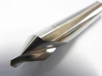
Centre drilling creates a small, precise indentation using a specialised centre drill. Its sole purpose is to provide an accurate starting point for the subsequent pilot hole, preventing the larger drill bit from slipping or drifting off-centre.
Drill machining (pilot holes)
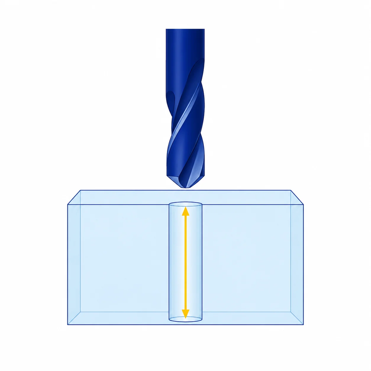
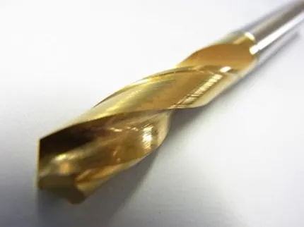
The drill bit is mounted on the machine spindle, rotated, and moved linearly into the workpiece. Because drilling involves repeated up-and-down motions, the resulting inner surface may show slight imperfections. For many applications — clearance holes, for example — a drilled hole is perfectly adequate on its own. When higher precision is needed, drilling serves as the preparation step for reaming, tapping, or counterboring.
Reaming
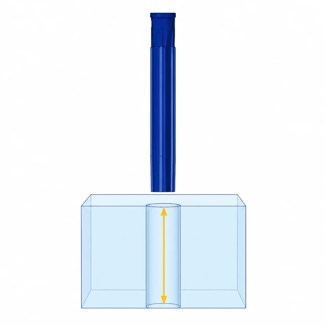
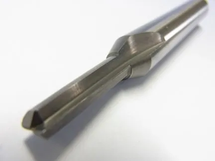
When you need a clean, perfectly round hole for press-fit pins or precision mating with other components, reaming is the answer. A reamer is slowly rotated through the drilled hole, removing a very small and controlled amount of material from the inner surface. The result is a smooth, accurate bore. Reaming is used when a tolerance of approximately ±0.01 mm relative to the hole diameter is required.
Tapping
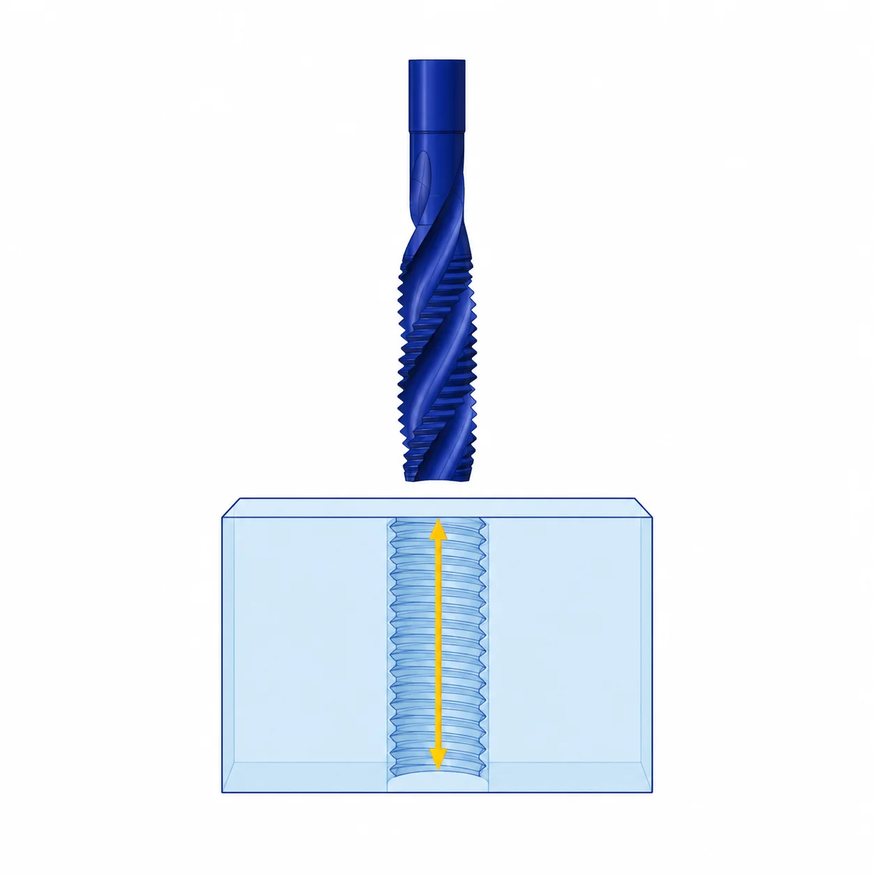
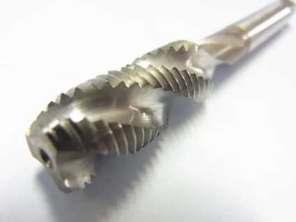
Tapping is the process of cutting an internal thread into a drilled hole so it can accept a screw or bolt. A specialised cutting tool called a tap is used, and in CNC machining a dedicated program (tap cycle) controls the feed and rotation precisely. Tapping is the standard choice whenever a hole needs to serve as a threaded fastening point.
Counterboring
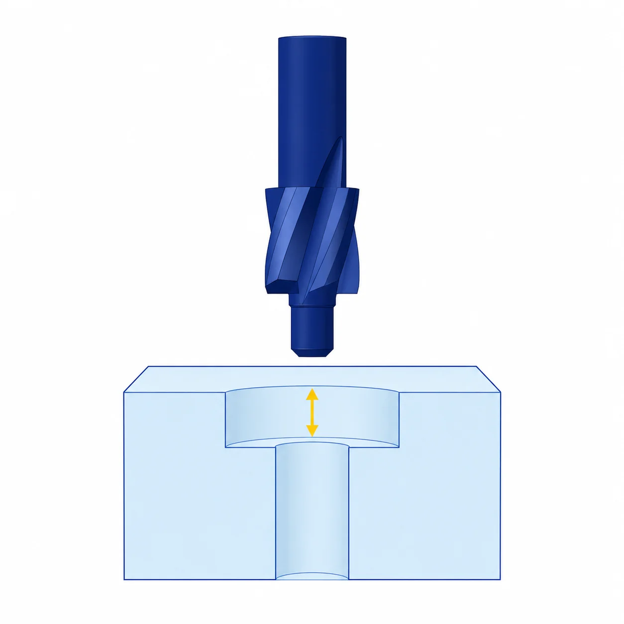
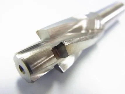
Counterboring enlarges the top portion of a hole so that a bolt or screw head can sit flush with — or below — the part surface. While a regular drill can produce a basic counterbore, dedicated counterboring tools deliver cleaner results and more consistent depth. This operation is essential for assemblies where protruding screw heads would interfere with other components.
Common hole design mistakes and how to avoid them
Even experienced designers sometimes run into issues that only become apparent during manufacturing. Below are two of the most frequent problems — and the design rules that prevent them.
Holes too close to the edge
During drilling, the cutting force pushes material outward. If a hole is placed very close to an edge, the remaining wall may not withstand this force, causing the side to bulge or deform. The problem is especially pronounced with threaded holes, where the tapping process adds further lateral stress.
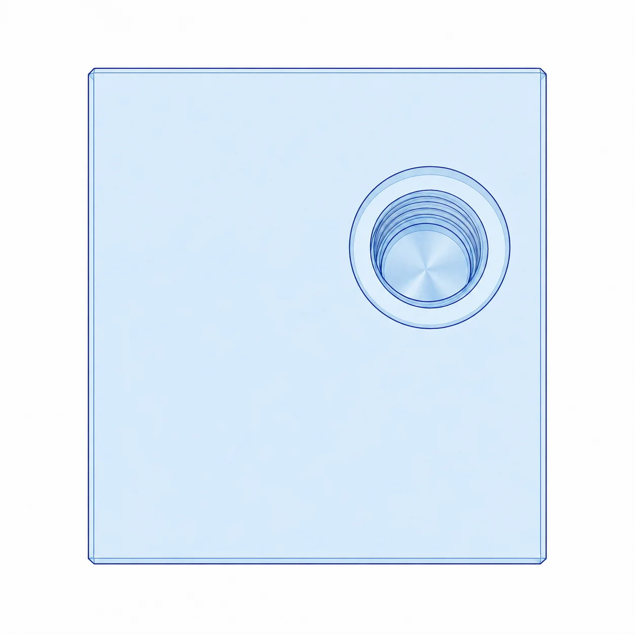
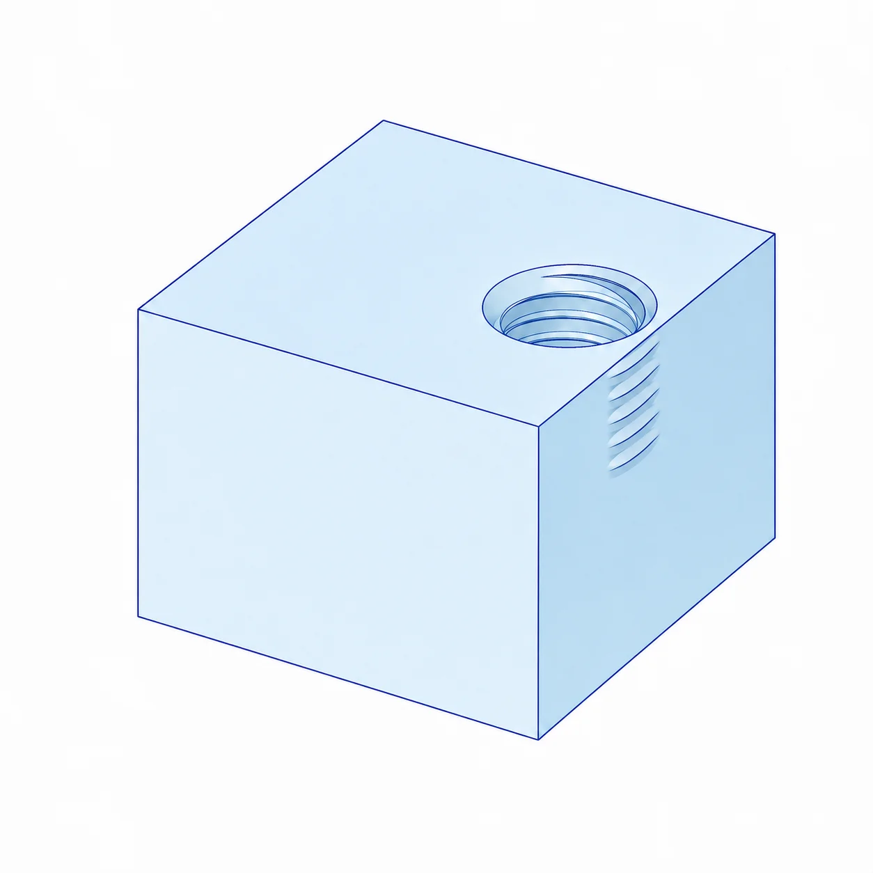
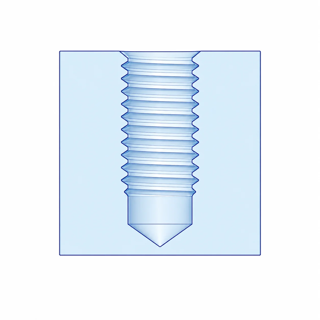
The general rule is to maintain a minimum distance from the edge of at least one hole diameter. For threaded holes, an even greater margin is recommended.
If the design makes it impossible to increase the edge distance, an alternative is to add extra material on the affected side before machining the hole. This can mitigate the bulging effect, though it introduces an additional machining step and increases cost.
Holes that are too deep
In standard hole machining, precision can reliably be achieved for depths of up to approximately eight times the hole diameter. Beyond that depth, the drill tends to bend, causing the hole to deviate from its intended axis and the diameter to widen progressively.
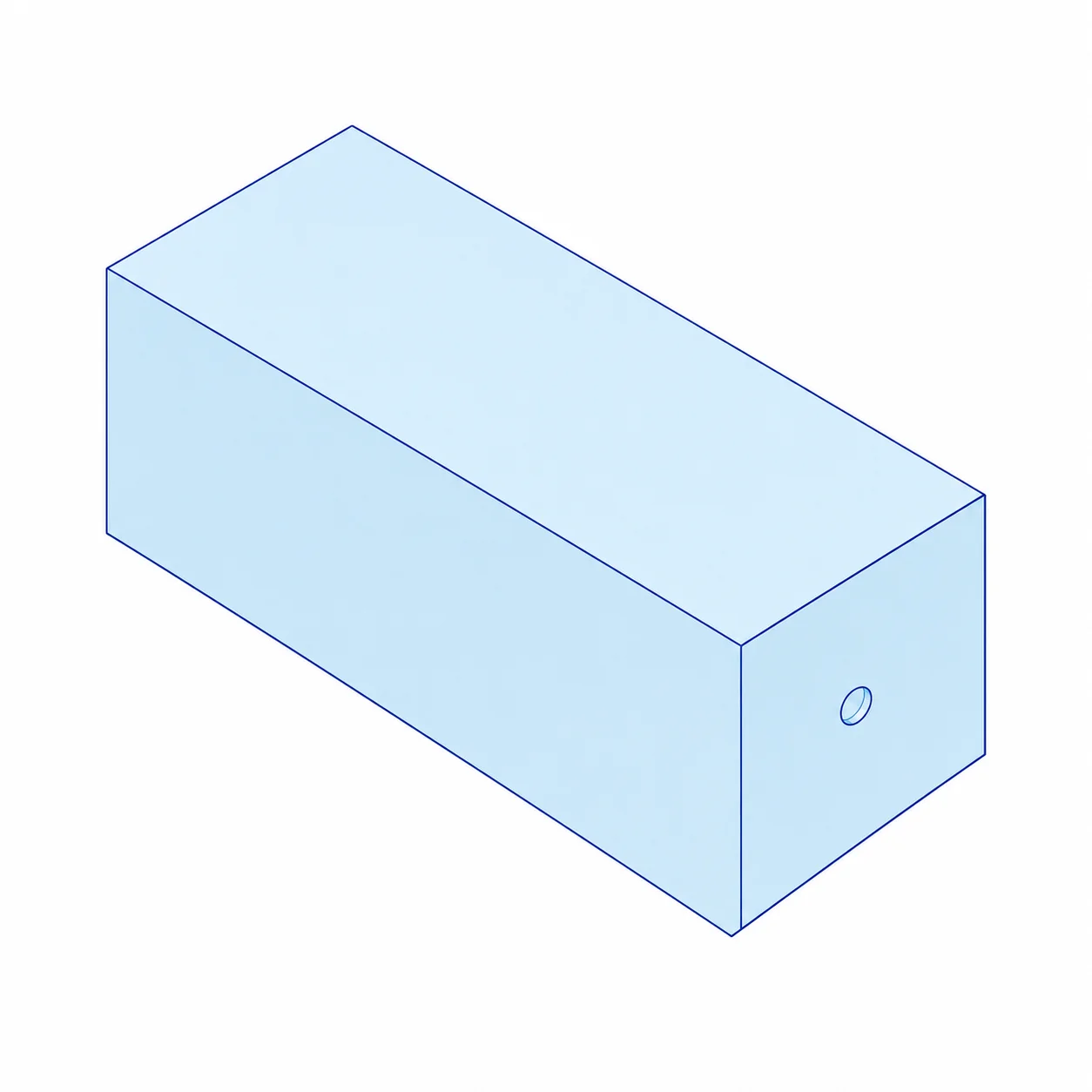

High-precision deep-hole machining methods such as honing or wire-cut electrical discharge machining (EDM) exist, but they come with significant cost and lead-time implications. As a general design rule, keep hole depth below eight times the diameter whenever possible.
For through-holes that must exceed this depth, one common approach is to drill halfway from each side of the part. This technique — sometimes called gun drilling — minimises bending by halving the effective drilling depth.
Key design rules at a glance
- Always start with a centre hole to guide the subsequent drill accurately.
- Choose the right finishing operation for the hole's function: reaming for precision fits, tapping for threads, counterboring for flush bolt heads.
- Keep holes at least one diameter away from any edge — more for threaded holes.
- Limit hole depth to roughly eight times the diameter to avoid bending and tolerance drift.
- For deep through-holes, consider drilling from both sides to reduce deviation.
Design and manufacturing each have their own constraints. When you understand the fundamentals of how holes are machined, you can design parts that meet functional requirements without creating unnecessary cost or risk on the production side.